The building blocks of a domotics circuit
Why domotics needs its own approach
In a classic installation the schema shows what happens: a line from the switch to the light point. With domotics that line disappears. The push button sits on a bus line or works wirelessly, and a controller switches the loads through output modules in the board. Anyone reading the schema therefore cannot see which button operates which light, because there is no drawn connection.
For an inspector or a colleague who maintains the installation later, that is a problem: the schema still has to tell how the installation is built. Trikker solves this with addresses. In this lesson you first get to know the building blocks; in the next lesson you link them with addresses.
The Domotics category
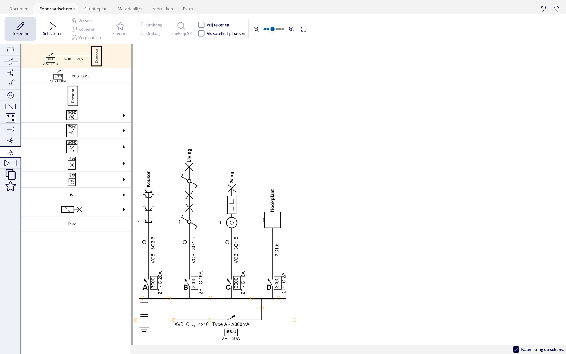
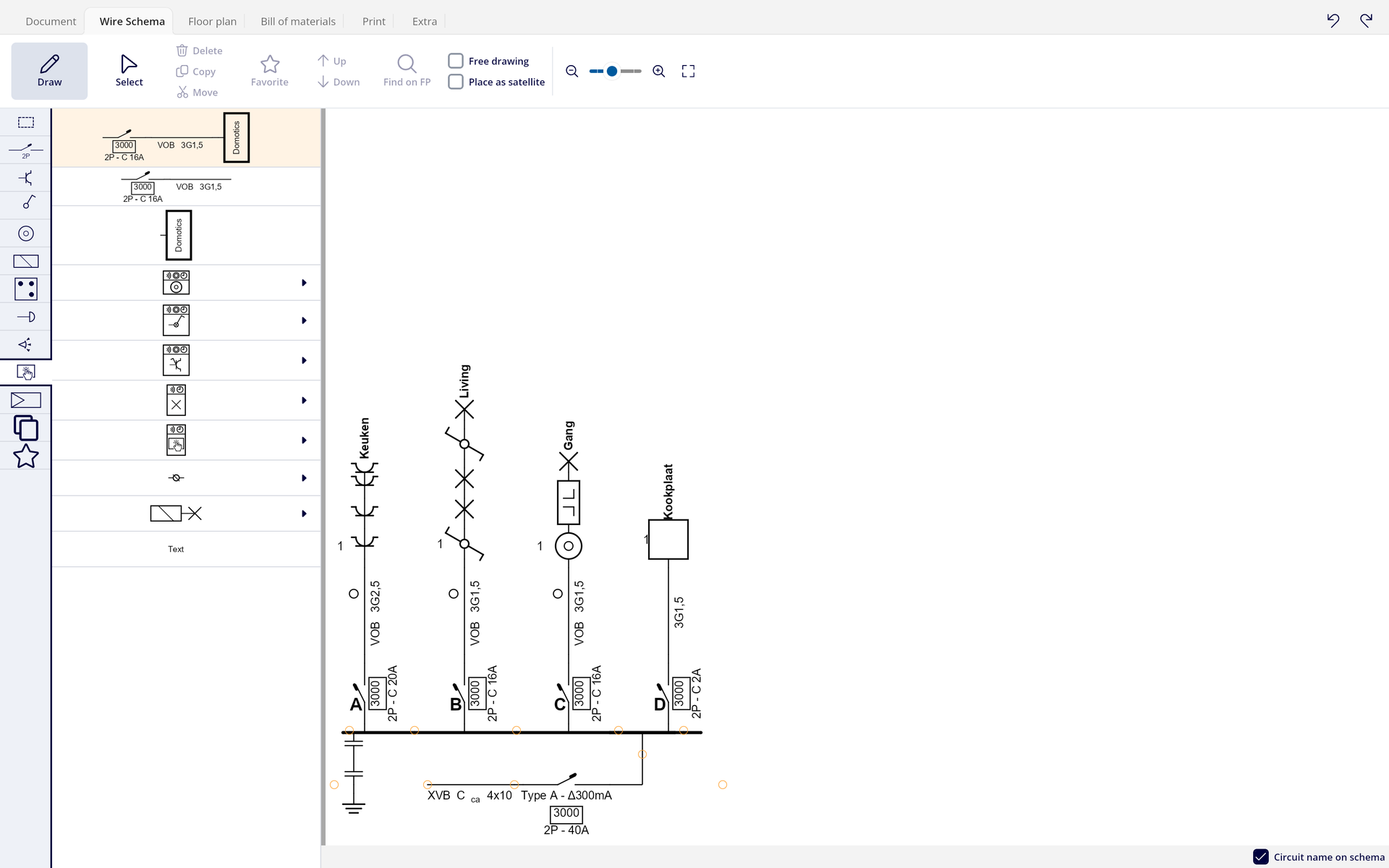
In the library you find the Domotics category. It holds everything to build a domotics circuit:
- a breaker with conduit and module, to start a domotics circuit;
- a standalone module symbol;
- domotics units: push button with one, two or four buttons, switch, socket and light point;
- a touchscreen unit, terminal and connection point;
- relay and dimmer variants.
The module symbol
The module is a rectangle with one supply point on the left and outputs on the right. Its height grows with whatever hangs below it, so you never have to stretch the symbol yourself. Five properties decide how the module looks:
- Module name puts a text inside the symbol, for example the product name or Controller.
- Output names gives the outputs their own name, in order. That name then replaces the sequence number on the schema.
- Mark is set to Yes by default: the module then counts itself in the numbering. On No it is skipped.
- Input symbol and Output symbol draw voltage symbols on the input and output side, so the same symbol can also serve as an inverter.
The control strip
Above a domotics unit sits a narrow strip with pictograms that shows how the point is operated. Four properties each drive one pictogram: Push button, Wireless, Programmed and Detection. The more you switch on, the wider the strip gets.
The strip only exists as the top part of such a combined symbol. You switch the properties on or off in the properties window of the unit itself.
Example: a lighting circuit in the living room
Say a house has a domotics controller in the board. You start the circuit with the breaker with conduit and module and give the module the name Controller. Below the module hangs an output for the ceiling light. At Output names you call that output Living. On the schema, Living now replaces a bare sequence number, and whoever reads the schema knows at once which output it is.
You also place a push button unit by the door. If it is a wireless button, you switch on Wireless: the strip shows a pictogram and you do not need to write a remark. How to link the button to the output you see in the next lesson.
Give outputs a meaningful name. A name like Living or Kitchen reads faster than 3 or 7, especially for someone who does not know the installation.
You will not find the strip as a standalone symbol in the library. It belongs to the domotics unit, and its properties are in the properties window of that unit.
Summary
- Domotics has no drawn connection between button and lamp; Trikker uses addresses.
- The Domotics category holds the module, units, touchscreen, terminals and relay and dimmer variants.
- The module grows by itself and has five properties for name, output names, numbering and voltage symbols.
- The control strip shows with four pictograms how a point is operated.
There are no comments for now.